Skip to content
  • Suomeksi
  • In English
  • Networking
    • WiFi/WLAN
    • MikroTik
    • Ubiquiti
  • Security
    • General
    • Wireless
  • Software
    • WiFi
    • WordPress

Category: WiFi

WiFi 2.4GHz band

The original Wi-Fi (also known as 802.11) used the 2.4GHz band. It is still the more popular band since virtually all devices support it. That makes it more crowded and it is also more prone to interference than the alternative 5GHz band.

WiFi 2.4GHz band

This article is a more technical in nature, but understanding underlying technology is the key to successful deployment and utilization.

Channels

The band covers 2,400–2,485GHz which makes it 85MHz wide. It was already split into 5MHz channels before WiFi was invented. 5MHz is too narrow to be very useful in computer networking, since narrow band can only transfer limited amount of data. The original 802.11 and its successor 802.11b used 22MHz channels which covered five 5MHz channels. The later 802.11g and 802.11n used more efficient OFD modulation with 20MHz channels.

In Europe (in ETSI jurisdiction) and in most of the world there are 13 separate 5MHz channels. In Japan there are 14 channels but in the U.S. only 11. Channels are referred to by its number or by its center frequency. In the illustration the channel numbers are on the left and the frequencies at the top. The bars denote the 20MHz bandwidth the WiFi channels use.


2.4GHz channels
2.4GHz channels

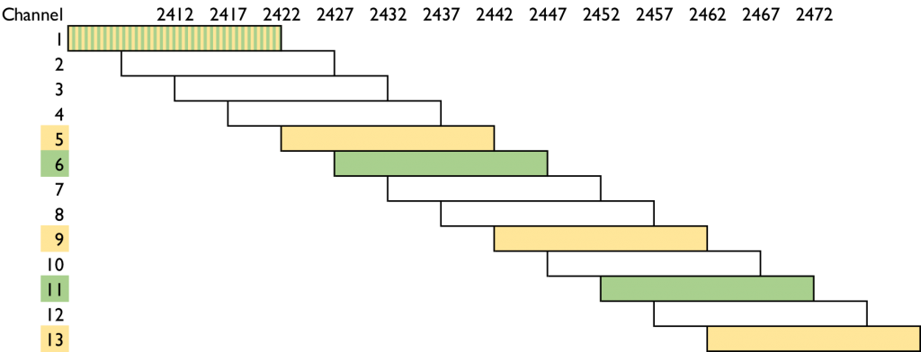
In theory the yellow bars 1, 5, 9 and 13 would form four distinct channels with no overlap. Unfortunately most WiFi radios assume wider 22MHz channels so they receive a signals from the adjacent channels as well. If the radio detects a transmission it will wait for the channel to vacate. This can make adjacent radios (on channels 1 and 5 for example) take turns, which halves the throughput.

In the U.S. you can only use three distinct channels: 1, 6 and 11. They are marked green in the illustration. There is one free 5MHz channel between them, so there won’t be any need for the turn taking. Three channels also suffices to form a grid in a plane where no adjacent radios will ever be on the same channel. You will run into trouble though, if your scene is not a plane: open stairs, atriums and the like or if the signal passes through the floors.

The access points on the market default to one of the American channels, so it is safest to stick to the same system also in Europe. If there are next door APs on channels 1 and 6 then your AP on channel 5 will wait for both to cease transmitting for it to get a turn. If you use 1, 6 and 11 you only need to wait for one AP only. Another problem is that all client devices don’t support channel 13, which may cause mysterious holes in coverage as the user moves between access points.

Coverage

The maximum transmission power on 2.4GHz is 100mW or 20dBm. That is more than enough since most mobile devices transmit below 20mW (13dBm). Since the connection is bidirectional there is no point of having an AP with large coverage if the clients cannot transmit back.

The wavelength of 2.4GHz is twice the wavelength of 5GHz which by law of nature means there is less attenuation. 2.4GHz signal will appear 6dB or quadruple stronger compared to 5GHz. This translates to much larger coverage in open space or better wall penetration. Metal will still block both signals and just a thin foil or mirrored glass is enough. In practice the better coverage of 2.4GHz often causes problems, since most devices will pick the stronger signal. That is 2.4GHz over 5GHz, even though we usually would like to steer the clients to 5GHz for more capacity and throughput and less interference. The solution is to turn down transmit power of the 2.4GHz by 6–7dB.

Interference

The WiFi uses unlicensed spectrum which is free for anyone to use as the term suggests. 2.4GHz is very popular and has many applications. Many wireless devices and gadgets use the same frequencies with no coordination whatsoever. Examples like burglar alarms, wireless CCTV cameras, motion detectors, video drones, BlueTooth… In case of a collision one or both of the devices just won’t work.

There are lot’s of interference sources on 2.4GHz as well. Devices with electrical motors, microwave owens and some light sources may cause interference. The latest menace is USB3 which just happens to use the same frequency. Many cheap USB3 cables have inefficient shielding, which may prevent using 2.4GHz WiFi at least on that computer. Interference is often a by-product which won’t have any effect on the device itself. It may be difficult to pinpoint the source without special equipment like a spectrum analyzer.

Congestion

Since all devices support 2.4GHz WiFi it is often deployed “just in case”. It can also be used to fill in coverage holes left in 5GHz. Therefore in practice all access points transmit on 2.4GHz causing congestion.

All WiFi devices listen on the channel before transmitting to avoid collisions. If the device detects a transmission it will wait and then listen again. In a congestion there will be many devices waiting and only one gets its turn at a time while others continue waiting. The waiting times can grow which translates to long delays and low throughput.

A couple of examples in downtown Helsinki:

995 APs on 2.4GHz and 4 on 5GHz

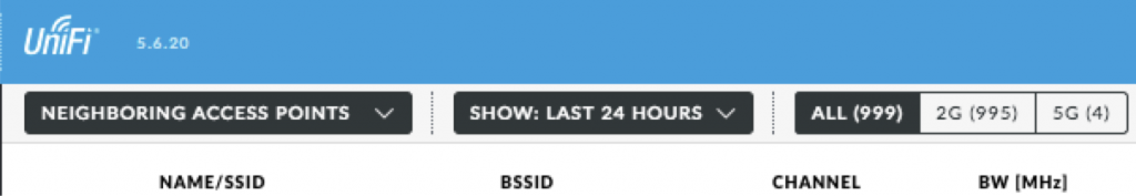
A UniFi controller reports on the neighbouring APs it detects. In this case 995 access points (not users!) were detected on 2.4GHz in the last 24 hours while on 5GHz there has been four.

Channel usage
2.4 and 5GHz channel usage

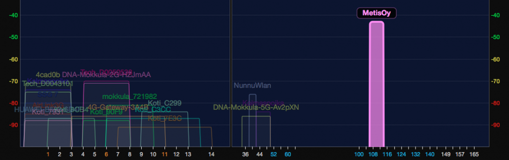
WiFi Explorer shows the signal strength as columns. The width of the column is the channel width. On the left there are 2.4GHz channels 1–14 and on the right the 5GHz channels 36–165. Quite a bit less crowded on 5GHz!

Recommendations

If you don’t need 2.4GHz then don’t deploy it. It is perfectly all right to turn it completely off. Some very old or cheap mobile devices may only support 2.4GHz WiFi, though. IoT devices like thermometers and motion detectors are new players on the market. Some of them only support 2.4GHz. In that case you need to deploy 2.4GHz of course. Just turn down the transmit power so no 5GHz capable device won’t associate with it by accident.

In theory 802.11n supports 40MHz channel width also on 2.4GHz. In theory this will more than double the throughput. In theory. In practice 40MHz channel requires devices to wait for silence on two channels at the same time before they can transmit. The end result may very well be less throughput. Another matter is that only one 40MHz channels will fit in the 2.4GHz band making it useful only in scenarios with only one access point. In 5GHz wider channels are the norm and they actually work.

Author Petri RiihikallioPosted on 23.01.201820.10.2018Categories WiFiLeave a comment on WiFi 2.4GHz band

How to build a working WiFi in an older residential house

Modern WiFi coverage is needed in older residential houses as well. It isn’t always easy to achieve. Here are a couple of design points to consider.

How to build a working WiFi in an older residential house

In a smaller, wooden house a single access point may provide good coverage for the entire building. Nice and easy. But if you have a multifloor brick and/or concrete construction, you are in for trouble. Many houses are built like bunkers: reinforced concrete floors and sturdy walls that kill all WiFi signals. You will need multiple access points per floor. For the access points you will need a wired distribution network. Wireless is only for the last hop to the device, the access point needs a wired feed. Unfortunately only 21st century houses tend to have high speed network cabling built in. In older buildings the distribution network is often the main challenge.

Wired Network

Using the power lines for networking is a popular alternative, if you search for solutions. Unfortunately the results are most often not even close to the expectations. This is easy to test. Just plug the powerline adapters to adjacent power sockets and test the throughput. It might be a measly 30 Mbps instead of the hundreds advertised on the box. With more distance the speed will drop even lower. If the sockets are in separate fuse circuits you need an electrician to bridge the circuits. But still you won’t get the throughput you need.

Another widely offered alternative is to use wireless for the distribution network. It is called Mesh WiFi, WiFi repeater or Wireless Distribution System (a.k.a. WDS). The inefficiency will cause problems because there will be so much wireless traffic going back and forth. The net effect is a slow network. In the best mesh access points there are two radios: one for the clients and one for the backhaul, but they tend to be pricey.

Most houses have telephone cables connecting the floors. In the best case the cabling is not used anymore at all. If the telephone cables are installed in tubes inside the walls, you can easily replace them with Ethernet cables. Every access point will need its own feed (cable), but there is not room for many cables in the tube. The professional solution is to put a network switch on every floor and run only one Ethernet cable between the floors. If you only need a couple of access points on a floor, you might get by using twin Ethernet cables. Actually, you can use a single Ethernet cable to transfer two 100 Mbps connections because only from gigabit up are all 8 wires used. With twin cables you can run 4 x 100 Mbps in a single tube. Is it reasonable to install 100 Mbps Ethernet today? In residential use it should be plenty for the next 10 years or so (unless you have fibre connection from the house). Even if the phone cables are installed on the surface, you may still use four wires to get speeds up to 100 Mbps. Either way, you can still use the old phone system to get a neat and inexpensive distribution network. If that is not possible, you need to run cables through ducts, a stairwell or on outer walls, increasing the amount of work to be done.

In every case the cabling job is best left to professionals. They have the tools to install and test the connections. Most electrical, telephone or data service shops do cabling. Ask for a couple of tenders and take your pick. Just make certain that all the cables will be tested and you get the report. A proper tester will cost well over a thousand Euros, so the handyman next door may not have one. All professionals do.

Wireless network

You will need multiple access points per floor to get good coverage through brick walls. Even if you can crank up an access point to cover the whole floor, the cell phone in the last room can’t reach back to the access point. With multiple access points the administration needs to be organized. Manually keeping just five access points in synch regarding all settings and updates is a chore. Ubiquiti has affordable access points and the central controller software is included. The Ruckus brand XClaim would be another alternative, but XClaim doesn’t seem to have a distributor in Finland at the time of writing.

The access points need power to operate. The neatest solution is to feed the power over the Ethernet (a.k.a. PoE). The network switch provides the power, so the switch needs to have a power supply big enough for all the access points. There are two standards for PoE: older 802.3af and later 802.3at (a.k.a. PoE+). Latest 802.11ac access points are power hungry and often require a PoE+ switch. Some vendors have their own, non-standard PoE solutions (often called “passive”). In that case it is best to stick with the same brand for access points and switches to ensure compatibility.

Links

  • Ubiquiti UniFi
  • Verkkokauppa.com UniFi (a Finnish retailer)
  • XClaim
  • AmpliFi (mesh network)
Author Petri RiihikallioPosted on 18.12.201719.12.2017Categories Ubiquiti, WiFiTags 802.11ac, PoE, Ubiquiti, XClaimLeave a comment on How to build a working WiFi in an older residential house

8 reasons to turn down the transmit power of your Wi-Fi

By default almost all WiFi access points transmit at full power (100mW on 2.4GHz). This gives maximum coverage and users see a good signal (“full bars”). However, there are good reasons to turn down the transmit power to a fraction of the maximum.

8 reasons to turn down the transmit power of your Wi-Fi

It even makes sense to start with minimum power and increase it until the necessary area is covered.

0. Wi-Fi is about sharing, not competing

In a congested environment it doesn’t matter if your access point is stronger than the neighbor’s. If your AP can receive other APs then it will share the air time with them by taking turns. All APs on the same channel will give other APs equal access to the spectrum. This is how 802.11 was written.
[Edit: I added this point as an afterthought, since this isn’t obvious to many users.]

1. Full power doesn’t increase coverage

Mobile devices like phones and tablets have very limited batteries. To minimize power consumption their radios typically max at 15mW (12dBm), while access points max at 100mW (20dBm) on 2.4GHz and 200mW (23dBm) on 5GHz. However, WiFi connection is always bidirectional. It does no good if the client can receive the AP if the AP can’t receive the client. Have you ever been unable to connect – even though you appear to have good signal? This is the reason.

The bidirectional connection is symmetrical. It doesn’t matter if the AP has a better antenna or is located higher up. The antenna gain and any attenuation factors work symmetrically in both directions. So a good antenna and good location will improve the connection in both directions. Unilateral transmit power increase will only work in one direction.

2. Roaming

In WiFi the client devices decide which access point they want to associate with and when to switch to next. (This is contrary to the mobile telephone network, where access points decide which one will serve which client.) Many devices are very reluctant to roam to another AP. They hold on to the first chosen one even when there is a much stronger AP next to the device. Only when the connection breaks will they associate with the next AP – and keep that connection to the end. This results in clients using far away access points with poor connections. By lowering the transmit power the connection will break sooner and the client will roam to a better access point.

This behaviour affects access point utilisation as well. In the worst scenario the access point by the entrance covers the entire office just barely. When users arrive their devices will associate with the entrance AP and keep using it for the rest of the day. The entrance AP is overloaded while other APs are idle.

3. Battery life

The access point informs the clients what its transmit power is (802.11h TPC, 802.11k TPC or Cisco DTPC). Mobile devices will adjust their transmit power level to match to save battery. The logic is that if the mobile device can receive the AP at that power level, the same applies in reverse as the symmetry was explained earlier. By setting the AP transmit power to 5mW (7dBm) for example, you can increase the battery life of the clients. Such a weak signal won’t penetrate walls, so you need more access points – see the next section Performance…

4. Performance

Back then access points were expensive and they were placed far apart. Now the price is no longer an issue, but WiFi performance is. By adding more access points there will be less clients per AP, hence more bandwidth per client.

Keep in mind that wires are always more efficient than radio waves. The faster and closer you can move the data from radio to wires, the better. That’s why increasing the number of low-powered access points is the key to a high performance WiFi network. Why low-power? See the next section Interference…

5. Interference

A powerful signal will interfere with neighbouring devices even if they are on different channels (frequencies). At high signal levels the whole device will act as an antenna and induction will cause superfluous signals in the circuits. This is why you need to keep access points at least 10′ (3m) apart or have a thick concrete wall in-between, preferably both.

Access points can still interfere with each other, even if there is enough distance. The WiFi channels are not absolute. While the transmission is on a certain channel, the signal bleeds to the neighbouring channels as well, albeit weaker. At high transmit power this weak signal will be strong enough to interfere.

6. Distortion

If you drive an amplifier at full power the output will distort. This is easy to test with a car radio: turn it on full blast and try to make sense of the lyrics. A distorted signal is hard to decode and in WiFi parlance this means transmission errors and retransmissions, which will slow down the network. You can increase performance by lowering the transmit power.

7. Neighbourliness

A strong signal will cause interference in a large area. Even though the extra milliwatts won’t benefit you, they will consume limited air time and interfere with all other WiFi networks in the area (look back at point 0 at the beginning of the article).

Think about it security wise as well: Why should anyone across the street be able to receive your WiFi signal?

8. Longer lifetime

Lower transmit power equals lower energy consumption equals less heat. Operating at lower temperature increases equipment lifetime. While access points are inexpensive, they tend to break at the most inconvenient time and place. You won’t notice the energy savings on your electricity bill, though.

Author Petri RiihikallioPosted on 21.10.201707.02.2022Categories WiFi207 Comments on 8 reasons to turn down the transmit power of your Wi-Fi

WiFi heat maps

It is fairly easy to create a heat map of a WiFi network that shows the signal level across the coverage area. What’s the use, what’s the benefit of surveying and is it worth paying for?

WiFi heat maps

There are many tools available to survey WiFi coverage and draw a heat map. In WiFi heat maps strong signal areas are often drawn in green, weaker signal areas in yellow and problem areas in red, which is the opposite of typical heat maps. If the whole office is inside the green area, does it prove that everything is working fine? It depends, there are different kinds of heat maps telling different aspects of the WiFi network.

Passive Surveying

A passive heat map is the most common one and straight forward to make. Start an application, load the floorplan and walk around marking the points of measurement on the floorplan. The application will calculate the signal between the measurement points and draw a heat map.

In a passive survey only the received signal strength is measured, in other words, how “loud” the access points are. All received access points and networks are plotted, so you can see how nearby networks might interfere with your network.

The problem with passive surveying is that only the received signal strength is recorded. Access points are more powerful than typical user devices, so the received signal strength tells little about connectivity or the quality of the connections. It is easy to create a good looking, green passive heat map: just crank up the transmit powers of all access points. This way the signal can be received as widely as possible, but the clients won’t be able to connect as widely, as the access point can’t receive their signal.

Active Surveying

In active surveying the measuring device is logged on to the network being measured. A connected device won’t report other access points or networks, so you need passive surveying for that. Instead, in active surveying you can map the quality of the connection to the access point: signal strength, bandwidth and error rate. You can also record where the device roams (i.e. switches to another access point), so you can manage roaming zones by adjusting access point transmit powers.

The problem with active surveying is that you are also measuring the measuring device itself. Different devices have different radios and antennas. A premium laptop will give very different results from a cheap cell phone. Even similar devices may have different WiFi drivers with different performance. In the worst cases the version the device driver matters. Active surveying should be performed using the least capable device the networks is going to support.

Interference Surveying

A spectrum analyzer records radio energy on a given frequency. Ordinary WiFi radios try to decode the signal, but can’t report distortions or other sources of interference. Spectrum analyzers don’t even try decode the signal, they just report the amount of energy detected. You need a special device to do interference surveys. In the survey you will detect interference sources like machinery, microwave ovens, cordless doorbells, BlueTooth devices, remote controlled toys and gadgets, cordless security cameras etc. The latest additions to the list are USB3 and LTE-U devices which may interfere with WiFi. On the heat map green areas mark the ares with least interference while red areas may cause problems for the WiFi network. Some analyzers can recognise the type of the interfering device from the interference pattern.

Predictive Surveying

A WiFi network is built into new buildings. How can you design a network for a building before it exists? You can open the CAD files for the building in a predictive survey application. The CAD files detail the locations and materials of walls and floors and the application knows how these will affect the signal. The application can calculate a predictive heat map for the future network. You can move access points on the screen and see the effect on coverage or you can let the application position the access points optimally. Of course you can use predictive tools for existing buildings, if you have the CAD files available. In predictive survey tools Finnish Ekahau is the market leader.

Challenges in Surveying

There are some common pitfalls in all survey types. The biggest one is change. The survey only records the current state. If someone places metal file cabinets close to an access point, the coverage may change completely. Even whether office doors are open or closed matters. Often doors are kept open during surveys, so the results won’t match the daily office use when the doors are closed. Humans contain a lot of water, which attenuates WiFi signal strongly. Twenty people in a conference room will yield a very different heat map when compared to one person doing the survey. The only way to find out about changed external networks and interference sources is to redo the passive and interference surveys periodically.

There are many sources of errors during measuring surveys. The differences in devices was already covered above. The human doing the survey will affect the results: if she happens to stand between the device and the access points or on the other side perhaps attenuating an external interference source. Furniture and materials can change how the WiFi signal attenuates and propagates. Just a decorative shiny film added for design somewhere can make a difference. Modeling all this for a predictive survey can be a daunting tas.

Is surveying useless, then? No, not at all! It reveals a lot of valuable information how the WiFi signal behaves in the area. You just need to keep in mind that a lot of green in a heat map doesn’t automatically prove that the network is performing well. You need to know what the different surveys tell about the network and its environment. Often you need to do multiple surveys for different purposes. You also need to redo the survey once in a while to discover what has changed.

It is a good idea to do an active survey after installing or upgrading a WiFi network. It is a way to see whether the project has met its design goals and can be used as a baseline for future improvements.

Links:
  • Ekahau
Author Petri RiihikallioPosted on 10.09.201704.05.2018Categories WiFiLeave a comment on WiFi heat maps

What are WiFi DFS frequencies and should I care?

The regulatory bodies are now strict about DFS requirements on WiFi access points. This applies to both new devices and updates to old ones. A simple firmware update may cause a lengthy delay before the network is operable.

What are WiFi DFS frequencies and should I care?

The 5 GHz band had been in use for aviation and weather radars before it was opened for WiFi use. There are still old radars all over the place and WiFi access points mustn’t interfere with them. If an access point detects a radar signal, it must change its channel, which usually breaks connections to its clients.

This mechanism is known as Dynamic Frequency Selection or DFS. When an access point starts up it must quietly listen on the channel for at least a minute before transmitting. Weather radars will continue to use channels 120–128 and on those channels the silent wait time is 10 minutes.

During use access points must keep looking for radar type signals and must automatically switch channel accordingly. After detecting a radar the access point mustn’t return to the channel for 30 minutes, even though the detected radar signal might have come from a helicopter flying by. Only the four lowest channels 36–48 (U-NII-1) and the highest odd channels 149–165 (U-NII-3) don’t require DFS.

These rules are old but they weren’t enforced for a long time. Now both European and U.S. authorities have changed their approach. The manufacturers have to abide by these rules or their products cannot be sold in these markets. This applies to both new devices and also to updates to old equipment.

How Does DFS effect WiFI?

The delay at startup has caused many panics among network administrators already. After a simple firmware update the WiFI wouldn’t appear on the air immediately, but after a delay. The 10 minute delay is long enough for panicked administrators to reboot all devices multiple times and change cables.

The first DFS implementations tended to be too sensitive and would classify all kinds of signals as radar, even though they weren’t. This caused unexplainable interruptions in the WiFi network. Fortunately these have been mostly solved by now.

One solution is to use only DFS free channels. All devices don’t support the  high U-NII-3 channels so this leaves us the lower channels from 36 to 48. In a quiet radio environment you can build your network on those channels. They tend to be crowded however, since every administrator wants to use them.

Because many administrators avoid the DFS channels, they are often unoccupied! Knowing the limitations brought by DFS you can still make use of them and get interference free coverage. In practice the access points don’t restart that often so the one minute delay isn’t really a problem. There aren’t tools available to detect radars nearby, but a one week test run is usually enough to see if DFS will cause problems on your network. There might be some occasional hiccups, but the client devices should reconnect on the new channel within 10 seconds without any manual intervention.

Links:

  • Weather radars in Finland
Author Petri RiihikallioPosted on 29.08.201727.11.2017Categories WiFi5 Comments on What are WiFi DFS frequencies and should I care?

Weather radars in Finland

Don’t use the same WiFi channel as the closest weather radar!

Weather radars in Finland

European weather radars use frequencies between 5,60 and 5,65 GHz. In WiFi parlance it means channels 120, 124 and 128. If a WiFi device detects a radar signal it will either change channel or go silent for a half an hour. Either way the connection will be dropped. Your safest bet is to avoid these channels. On the other hand, there are just ten weather radars in Finland and they are pretty far apart. Do you need to avoid a channel in use in Utajärvi if you are in Helsinki? No. Usually it suffices to avoid the frequency used by the nearest radar.

Don’t be surprised when the WiFi doesn’t appear immediately. New and recently upgraded access points will listen for ten minutes for radar signals on these channels. This doesn’t sound good, but on the other hand these channels have least traffic for the very same reason.

Here is the current (3/2017) list of frequencies:

Name

Established

Position
(WGS84)

Height
(AMSL)

Frequency
(MHz)

WiFi Channel

Anjalankoski

1994

60.9039N
27.1081E

139 m

5638

128

Ikaalinen

1994

61.7673 N
23.0764E

153 m

5644

128

Kesälahti

2014

61.9070N
29.7977E

174 m

5610

124

Korppoo

1997

60.1285N
21.6434E

61 m

5620

124

Kuopio

1995

62.8626N
27.3815E

268 m

5615

124

Luosto

2000

67.1391N
26.8969E

533 m

5618

124

Petäjävesi

2015

62.3045N
25.4401E

271 m

5628

124

Utajärvi

1997

64.7749N
26.3189E

118 m

5608

120

Vantaa

1994

60.2706N
24.8690E

82 m

5649

128

Vimpeli

2005

63.1048N
23.8209E

200 m

5639

128

This is an example of radar interference. The narrow, straight patch of ”rain” between Helsinki and Tallinn is a caused by a transmitter on channel 128. The transmitter is either in Tallinn or on the sea, because the the beam is so narrow. A transmitter closer by would cause a wider sector of interference.

Weather radar

Links:

  • Weather radars in Europe
Author Petri RiihikallioPosted on 12.01.201708.11.2022Categories WiFi2 Comments on Weather radars in Finland

Alright, it’s 802.11 but what are the characters? (a, b, g, n, ac)

What are 802.11a, 802.11b, 802.11g, 802.11n and 802.11ac?

Alright, it’s 802.11 but what are the characters? (a, b, g, n, ac)

Originally WiFi or 802.11 was designed for barcode scanners. In a warehouse cords were inpractical, so going cordless was logical. Bandwidth requirements were very modest, so speed was not a primary design objective. This is the basis for all enterprise wireless networks of today providing videoconferencing and high speed database connections. The change has been gradual:


Max speed
/ radio

Frequency
(GHz)

Year

802.11

2 Mbps

2,4

1997

802.11a

54 Mbps

5

1999

802.11b

11 Mbps

2,4

1999

802.11g

54 Mbps

2,4

2003

802.11n

150 Mbps

2,4 & 5

2009

802.11ac

867 Mbps

5

2013

802.11ax

?

?

(2019)

The first redesign was 802.11a. It offered increased speed, but used the new 5 GHz band. 5 GHz radios were expensive and A never really took off. It was B, that used the 2,4 GHz band that really created the market. G brought the speeds of A to the less expensive 2,4 GHz band. N added even more speed and N was defined for both bands. 5 GHz radios were still more expensive, so cheaper devices and access points only had 2,4 GHz radios. The latest is AC, which is only defined for 5 GHz, but in practice all devices and access points are compatible with older standards (so they support also 2,4 GHz).

Isn't the maximum speed of 802.11n 600 Mbps? Yes, it is. N introduced MIMO (Multiple Input, Multiple Output) radios that could use multiple connections (four at max.) 4 x 150 Mbps is 600 Mbps. In AC there can be 8 radios that can connect to multiple clients at the same time (MU-MIMO or Multi-User MIMO). In practice mobile phones have a single radio, tablets may have two and laptops four. Each radio eats up batteries (and also adds to the manufacturing cost).

Why doesn't my device ever report these maximum speeds? In N it was possible to bond two 20 MHz channels to create a 40 MHz channel, which can transfer over twice the data. The maximum speeds are calculated using these wide channels. In AC the maximum is eight channels or 160 MHz channel width. The channel width is set at the access point, so if the access point is only using the default single channel then the speed will be limited to that. The 2,4 GHz band has so few channels that channel bonding is practical only in the 5 GHz band.

Author Petri RiihikallioPosted on 05.01.201731.01.2017Categories WiFiTags 802.11acLeave a comment on Alright, it’s 802.11 but what are the characters? (a, b, g, n, ac)

WLAN, Wi-Fi, WiFi or 802.11 – what’s the difference?

They all mean the same thing

WLAN, Wi-Fi, WiFi or 802.11 – what’s the difference?

In Europe the acronym WLAN is widely used. It stands for Wireless LAN or Wireless Local Are Network. WLAN is not a trademark, so it can be used freely. On the other hand, it is easily confused with VLAN or Virtual LAN. VLAN is a wired LAN technology that can be used to separate traffic in the wired network.

Wi-Fi is a trademark owned by Wi-Fi Alliance. Wi-Fi Alliance defines standards and tests for interoperability between Wi-Fi products. Certified products will connect with each other. In practice all products are certified by Wi-Fi Alliance, although it does not have any official status. The term Wi-Fi is in wide use in the Americas, although the dash has started to disappear: WiFi.

802.11 is a technical standard for wireless networks defined by IEEE or Institute of Electrical and Electronics Engineers. After the original 802.11 there have been addendums and extensions, that have a character as a name: a, b etc. After z the naming was continued with aa, ab, ac, ad etc.

Links

  • Wi-Fi Alliance
  • IEEE
Author Petri RiihikallioPosted on 04.01.201705.01.2017Categories WiFiTags VLAN3 Comments on WLAN, Wi-Fi, WiFi or 802.11 – what’s the difference?

How secure is your WiFi?

Do you have a shared password to the WiFi network? When was it last changed? Hasn’t anyone left the company since?

How secure is your WiFi?

At first WiFi networks were unsecured. However, radio waves penetrate through walls, so eavesdropping is very simple even from a distance – encryption was required. The first method was Wired Equivalent Privacy or WEP. WEP was weak from the first day on, but yet the breaking of WEP caught the industry pants down. A new method was needed fast – WPA or Wi-Fi Protected Access was created, also known as TKIP. WPA was improved upon and today WPA2 is the preferred choice. WPA2 is fast and presently a trusted method for securing WiFi traffic.

There are two flavors of WPA2: Personal and Enterprise. In Personal there is one, shared password for the whole network. Anyone who knows the password can join the network and listen on the traffic. WPA2 Personal is good for personal and home use, why not for a small office as well. In business use people come and go, though, and the password should be changed every time anyone leaves the company. Nobody should have access to the company network after leaving or being laid off. Still, WPA2 Personal is the most common way of securing WiFi networks.

WPA2 Enterprise requires that every user has a username and a password. This is the case in Windows Active Directory (AD). You can install Network Policy Server role (NPS) to a Windows Server to provide RADIUS service to the access points (AP). The APs will verify each user’s name and password with the RADIUS server (e.g. NPS) before allowing the user to access the network. By removing or disabling a user account in the AD you can deny access to the WiFi network as well. There is no need for additional equipment or software. In practice all APs support WPA2 Enterprise and the NPS role can be installed on AD Domain Controllers (DC).

Read more:

  • WPA3 is the latest Wi-Fi Protected Access
Author Petri RiihikallioPosted on 03.01.201705.11.2018Categories WiFi, WirelessTags WPA2Leave a comment on How secure is your WiFi?

How can a single user cripple the WiFi network?

..and what is Airtime Fairness?

How can a single user cripple the WiFi network?

Wireless network is a shared media, where only a singe device can transmit at a time. Every device must wait for its turn and gets to transmit eventually. The problem is that the transmit speed depends on signal quality: distance and interference. Close to the access points the transmit speed can be hundreds of megabits per second, while at the edge of the network it is one megabit per second. Users have typically have quite similar needs for data transfer, it is just that some user’s bits are transferred more quickly than other’s. That is, when the device at the network’s edge gets its turn, it will use several hunded times more time – while everyone else waits. One device can use 90% of the time capacity of the network, even though the amount of data is the same. The problem has grown worse over time, because WiFi speeds have increased, but all legacy devices and speeds are still supported.

Equipment vendors have a simple solution to sell: Airtime Fairness or ATF, which is found in many systems.  ATF means that the access point will transmit packets to slower devices less often. It used to be that all devices were treated equally, but in ATF the speed of the device affects who gets the turn. Older devices (using older standards) and devices further away from the access point will get even slower service, while the total throughput of the network does increase.

The access point cannot control how devices transmit. All devices compete for sending on an equal basis, but the access point will favour the faster clients when responding. Often the traffic is biased on downloads and that’s when ATF can improve the throughput.

Airtime Fairness is a good solution for intermittent problems, but it is still better to design the network so that all users are covered. Adding access points where needed will guarantee all users with a fast connection. Airtime Fairness can cover up design flaws up to a point, but it cannot fix them.


Author Petri RiihikallioPosted on 02.01.201725.04.2017Categories WiFiTags Airtime FairnessLeave a comment on How can a single user cripple the WiFi network?

Posts pagination

Previous page Page 1 Page 2 Page 3 Next page
Wi-Fi symbol

Metis Oy

  • Front Page
  • Fix your WiFi network!
  • Contact
  • Petri Riihikallio

Latest articles

  • Fix GCP UniFi Controller certificate issue
  • CWNE#307, Petri Riihikallio
  • Decibels
  • Wi-Fi Roaming
  • Automatic Wi-Fi channel management
  • WPA3 is the latest Wi-Fi Protected Access
  • Tuning your Wi-Fi by adjusting transfer rates
  • Increase your cell phone battery life with a small change in the Wi-Fi network
  • Wi-Fi Repeaters, WDS, Mesh and Other Wireless Backbones
  • How many users can one Wi-Fi access point support?
  • Networking
    • WiFi/WLAN
    • MikroTik
    • Ubiquiti
  • Security
    • General
    • Wireless
  • Software
    • WiFi
    • WordPress
Metis.fi Proudly powered by WordPress